Before we being, there are several things to be noted about this drivetrain swap.
It is not technically very difficult, but requires a lot of labor
There is cutting and welding that must be done to the vehicle
There is some wiring that will need to be fabricated
If you are not completely comfortable doing all of the above, you should not attempt this swap as some processes will be difficult to reverse. That aside, if you are confident in your ability to perform this modification, lets move on to what AWD parts you need. I decided to split this up into what you ABSOLUTELY must have and what parts make the job much easier.
Required AWD Parts
Transmission
Transfer case
Front axles
Drive shaft
Exhaust
Fuel tank and shield
Rear subframe
Rear axles
Rear differential
Swaybar
Rear knuckles
E-brake cables
AWD Flywheel
Recommended AWD Parts (In addition to the above)
AWD fuel tank connectors
AWD subframe rear bolts
AWD drive shaft and exhaust brackets (spot welded in the tunnel)
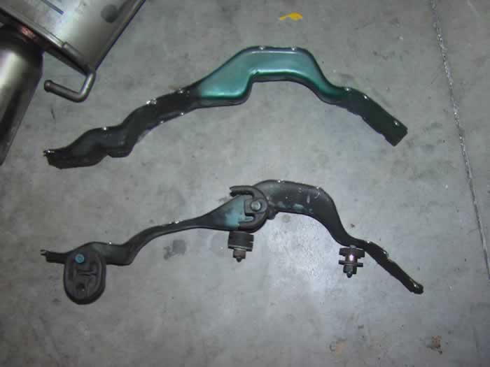
Entire AWD rear suspension assembly (all control arms)
STARTING THE SWAP
All the custom work for the entire swap can be done in the following steps:
Installing the gas tank
Installing the rear suspension
Installing the driveshaft and exhaust
Dissassembly of FWD
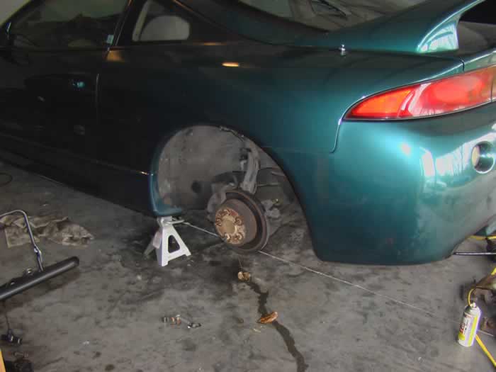
Assuming you have all the parts you need, we'll move onto the first step of the AWD conversion. Fortunately it's simple, the entire rear FWD suspension assembly must be taken out of the car. To save time, I took everything out as one whole piece. The e-brake cables have to be disconnected from the parking brake handle inside the car. You'll have to pull up the carpet to remove a couple bolts that hold the cables to the car, both inside and underneath. With those bolts out, you can pry the cables out of the car. This is a real pain so take your time.
Once the cables are disconnected, unbolt the upper control arms and trailing arms from the frame. You need to pull the rubber plug out of the body to remove the large bolt holding the trailing arm. Next, disconnect the brakes lines. Now support the rear assembly with jacks and remove the four bolts holding the subframe to the car. (Note: If your car has ABS, you will need to unplug the ABS sensors on the top of the subframe to avoid snagging the sensor wires.) At this point, just lower and remove the subframe.
The next task is to remove the FWD gas tank. From inside the car, unplug the fuel pump connector and fuel level sender connector along with all of the fuel lines. Underneath the car, the filler and vent hose must be disconnected. There are several bolts holding in the tank, remove them and lower the tank. Be careful here, if there is gas still in the tank you may end up with it in your face.
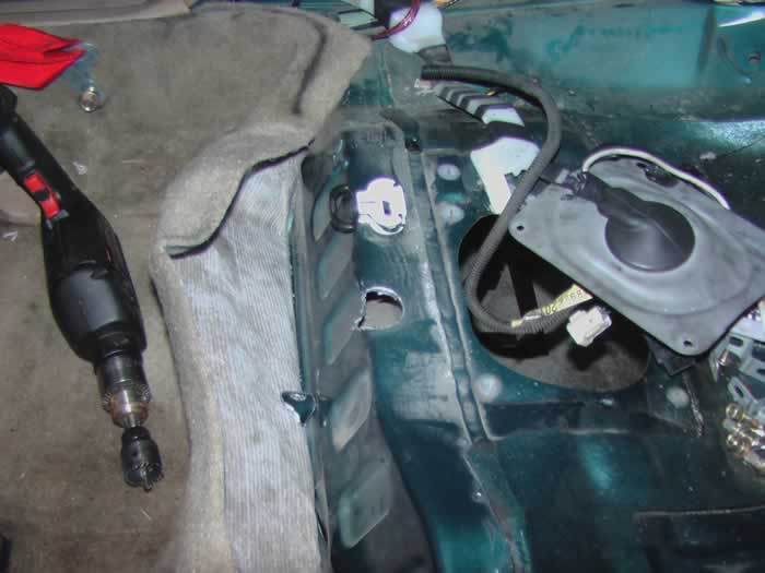
Installation of AWD Gas Tank With the rear subframe and gas tank gone, the back end of your car should be looking pretty empty. Time to fill all that space with the new AWD components. We'll get started with the AWD gas tank. The AWD gas tank mounts into the car with straps instead of bolting in like the FWD tank. To accommodate for this, the factory FWD tank mounts must be cut out. With the stock mounts removed, new bolts must be placed to support the AWD tank. The holes are already in the sheet metal, bolts just need to be placed in there. (See Figure) I used a holesaw and cut holes from the inside of the car (See Figure) from there I could drop bolts down. I placed a nut on the end of each bolt and tightened them down. (See Figure) This way if I ever have to remove the gas tank, I won't have to pull the carpet up on the inside to put a socket on the bolts. Simple enough. On to the next step!
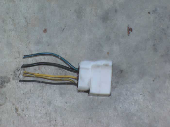
Before the new gas tank can be fitted into the car, we have to build a wiring harness to accommodate the dual sender setup of the AWD tank. The FWD fuel pump connector is two pin and the FWD fuel level sender is three pin. On the AWD tank, the fuel pump connector is six pin (See Figure) and the secondary sender is two pin. What I did was wire the AWD sending units into the existing FWD sender harness. I just cut off the connector and wired them up.
Here are the pinouts:
On the AWD Passenger Side Fuel Pump/Sender Connector
Thick blue/black wire is fuel pump power and is connected to the same wire on the 2 pin FWD fuel pump harness
Thick black wire is the fuel pump ground and is connected to the same wire on the 2 pin FWD fuel pump harness
Thin yellow/black wire is the sender feed to the second sender and is wired into the yellow/black coming from the other sender
Thin black wire is the sender ground and is wired into the ground wire on the FWD 3 pin sender harness
Thin yellow wire is the low gas light wire and is wired into the non-yellow wire on the FWD 3 pin sender harness
On the AWD Driver Side Sender Connector
Thin yellow/black wire is connected to the yellow black wire coming from the passenger side sender
Thin yellow wire goes to the fuel gauge and is connected to the yellow wire in the FWD 3 pin sender harness
Sorry that there isn't a diagram, but if you print this out and go look at the wires, it will make sense. Having the AWD fuel pump connectors makes this a snap as you simply have to solder the right wires together. Without the connectors, you will have to come up with something or possibly use crimp connectors. With the wiring harness made and the tank mounts dropped in. Lift the tank into place and bolt the support straps down. (Note: The FWD does not have a removable plate over the driver's side AWD sender. I choose not to cut a new one into the body; you may do so if you wish.) Plug up your new wiring harness to both senders, connect all the fuel lines, bolt on the gas tank shield, and you are done. At this point, I put a gallon of gas in the tank and fired the car up to make sure there were no leaks and both the fuel pump and gauge were operating correctly.
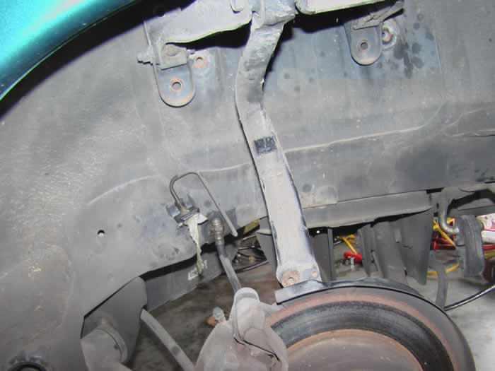
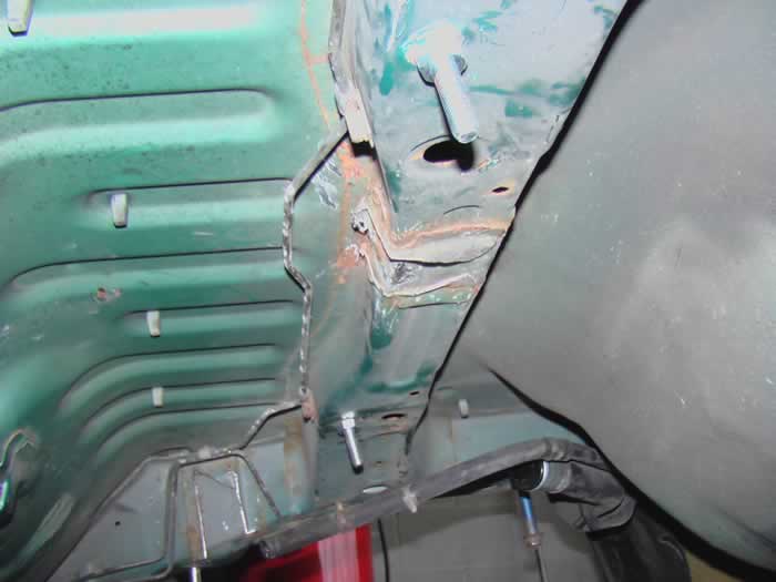
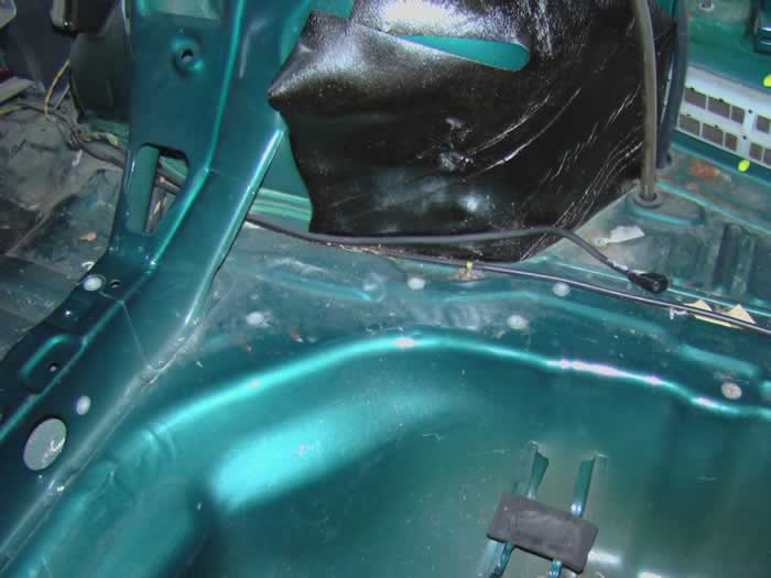
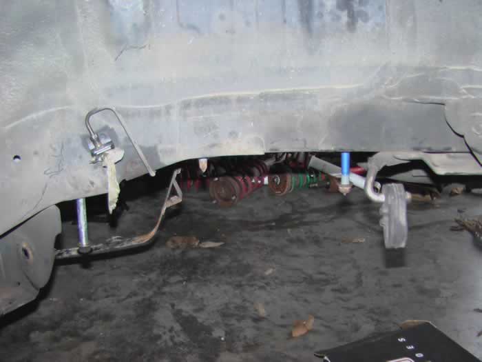
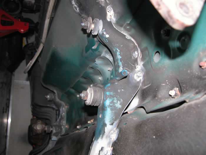
Installation of AWD Rear Suspension The next big step is mounting the AWD subframe. This requires some cutting into the FWD body to put in the required bolts. For the rear bolts see Figure for the location in which to start cutting. I used a Dremel tool with cut off wheels to cut away the layers of metal. Be sure to have a lot of wheels handy as the steel will eat them up quickly. Once you cut away the top sheet metal you will see something like Figure. Cut off the top of the bolt holder to reveal the rear subframe bolt. Push the old FWD bolt out and drop in the new AWD bolt if you have it. If not, you will have to cut away the bolt holder so that the FWD bolt will drop down far enough to attach the thicker AWD subframe.
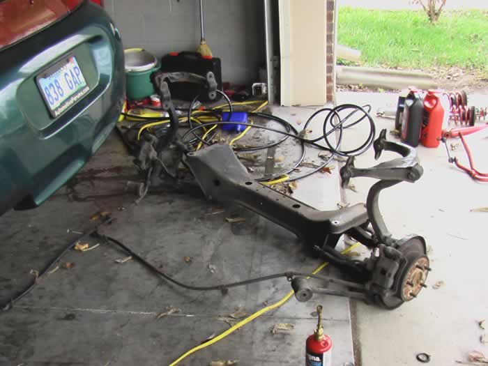
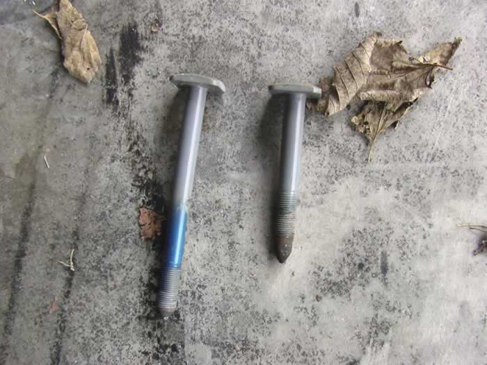
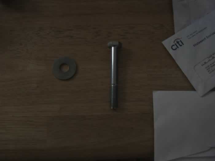
To install the front AWD mounts is a similar process. See Figure for the approximate location to cut into the body. For these mounts I used a holesaw again to cut into the frame. I got a proper length grade 8 bolt and thick fender washer for each side. I dropped the washer down into the frame rail and then fished the bolt through it and out the bottom. (See Figure) With both new bolts installed, but out the old FWD subframe mount (See Figure) and raise the AWD subframe into place. (Note: Be careful when raising the AWD subframe as you may push the mounting bolts back up through the top of the car.) With the AWD subframe supported in position, tighten the mounting bolts to spec. Take a step back and marvel at the progress you've made so far. If you opted not to install the rear diff, axles, and control arms with the subframe (It's far easier to get the subframe in place with all that stuff removed as it weighs considerably less) now is the time to finish installing the rear end of the AWD car. (See Figure)
Installation of Driveshaft and Exhaust
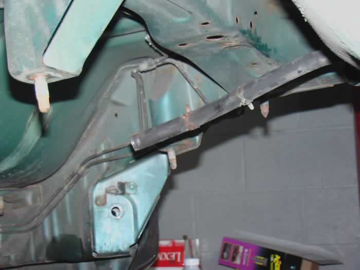
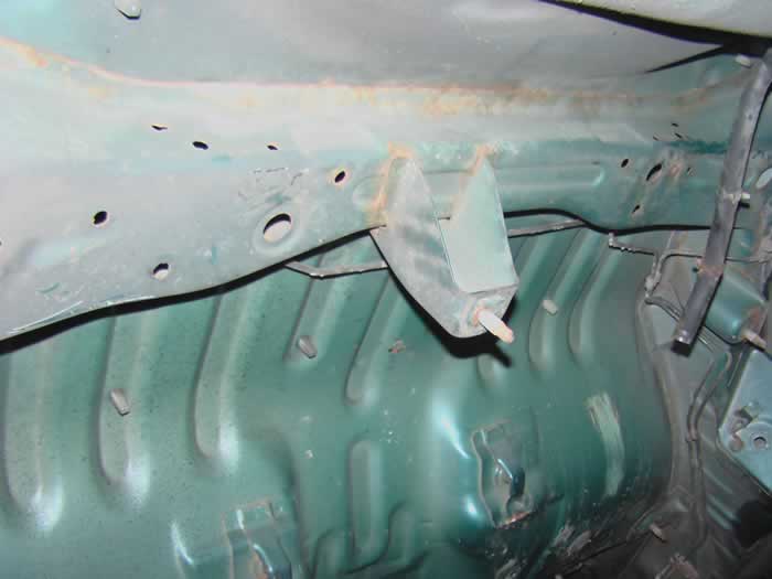
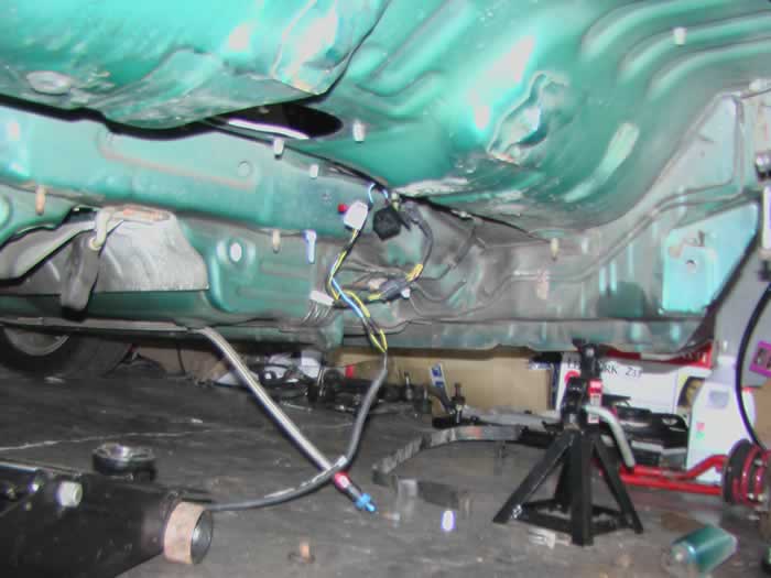
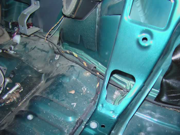
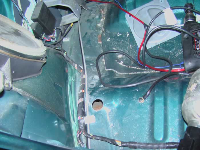
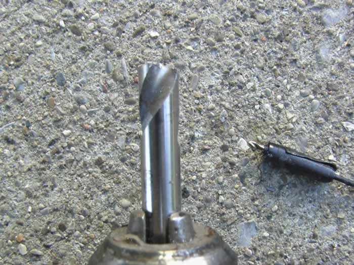
By now we have installed the AWD gas tank and rear suspension and drivetrain assembly. Not bad, the only real custom work left is to mount the driveshaft and AWD exhaust. THIS WILL REQUIRE A WELDER. If you have purchased and AWD parts car for this swap (as you should have!) you will need to drill off the two brackets in the tunnel that hold the driveshaft. The rear bracket is right in front of the gas tank (See Figure) and the front bracket is half way up the tunnel towards the front of the car (See Figure) Now, if you didn't get a parts car, you will have to fabricate a bracket to mount in front of the gas tank, but if you look, the FWD has the same mid-tunnel bracket as the AWD. (See Figure) The only difference is that the FWD bracket does not have exhaust hangers or studs to mount the driveshaft. If you can come up with a creative way to add studs and hangers to the existing bracket, you can save yourself some time. For simplicities sake, I chose to drill both brackets off the AWD and weld them on the FWD. (Note: The easiest way to drill of the brackets is to drill out the spot weld with a special spot weld removal drill bit 'See Figure'. I purchased mine from Pelican Parts for about $18 shipped.) Alignment is not a problem. For the mid-tunnel bracket, just weld the AWD one on right over top of the spot that you removed the FWD bracket. For the bracket in the back, it is self locating. It will fit snugly into the tunnel when it is lined up. One last thing is to add a stud to the rear drive shaft bracket in order to completely bolt up one of the AWD exhaust hangers. Adding this stud is not totally necessary as the hanger has two mounting points and one of the studs is already on the FWD (old fuel tank mount) I went ahead and added the other stud to finish the job.
Once the brackets are welded on, go ahead and bolt up your driveshaft to the rear differential and the brackets and attach the AWD exhaust. At this point all of the custom work is done. You just need to swap the FWD transmission for the AWD unit along with the appropriate axles, slap on the X-case and go enjoy putting power to all four wheels!
 AF Project Vehicle | Corporate