How to Read Compressor Flow Maps
This article is meant to help those who are considering either turbo charging their N/A car or upgrading their factory turbo to a bigger unit. For the purposes of this document, it is assumed that anyone reading is familiar with some basic turbo terminology and function along with some simple math.
Turbo terms to know:
- Compressor and Turbine wheels
- Wheel “trim”
- Compressor and Turbine Housing A/R
These items are the key elements that define a turbocharger and determine its flow characteristics. If you don’t already know how to interpret information about A/R or wheel trims and sizes, try searching the boards here at AF or looking online. I know Garrett has a lot of info on their site. (www.egarrett.com)
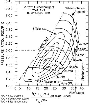
For those ready to dive into the vast world of turbo selection, we’ll start by looking at a sample flow map.
From the top of the chart we can see that this is a Garret TO4B turbo with and S-3 compressor wheel.
Understanding the Axis:
- First we will start by looking at air flow through the turbo measured on the x-axis. Garrett uses lb/min on their maps while other companies like Mitsubishi use cubic feet per minute (cfm). Since I think it’s easier to work with cfm, we’ll convert. Every 10 lb/min is equal to 144.72 cfm, remember this.
- The pressure ratio measured on the y-axis is merely the ratio of air pressure leaving to the turbo to air pressure entering the turbo. Since atmospheric pressure at sea level is 14.7 psi, if you were to run 29.4 psi of boost, the pressure ratio would be 2.
Understanding Information within the Map:
- The oblong ovals on the chart or “islands” as they are called represent the efficiency of the turbo in that range. As you can see on this map, the most efficient operation (73%) is in the very center of the chart. This is general characteristic of most turbochargers. Without getting into the thermodynamics of adiabatic heat-pumps, we’ll just say that efficiency is a measure of how much excess heat the turbo puts into the compressed air coming out of the outlet. So intuitively, more efficient is better.
- Wheel rotational speed is simply the rpm at which the compressor wheel is spinning.
- The choke point, which is usually not indicated on flow maps, is the maximum flow rating the turbo is capable of regardless of pressure or efficiency.
- Beyond the surge limit on the left of the plot, compressor surge occurs. In laymen’s terms, this phenomenon is caused by a back pressure wave entering the exit of the compressor housing and disrupting flow through the compressor wheel. Surge will kill turbos and is to be avoided at all costs.
Selecting a Turbo
Calculating your Engine’s Flow Requirements
Now that you can read and understand a compressor flow map, its time to figure out how to match a turbo to your engine, this involves selecting the proper compressor and turbine wheels along with the right combination of housing A/R. A mismatched turbo could not only result is extreme lag, but also wasted potential as a turbo can easily outflow an engine. I.e. bigger is not always better.
The only real calculation that needs to be done is to determine how much air you engine is actually flowing. This depends on a number of things including the RPM, absolute temperature (Rankin, equal to 460 + Fahrenheit temp), absolute manifold pressure (psi, equal to boost pressure plus atmospheric pressure), and lastly the engine volumetric flow or EVF in cfm.
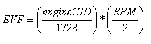
First to calculate EVF use the following equation:
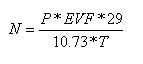
Next we’ll use EVF to calculate the amount of air in lb/min the engine is flowing under boost and at temperature using this equation:
Where N is the airflow in lb/min, P is the absolute pressure in psi, and T is the absolute ambient temperature in Rankin.
Finally, multiply N by the volumetric efficiency of your engine (VE). This compensates for the fact that upon every cycle of the engine, not all of the old air/fuel mix in the cylinders is forced out the exhaust. Thus there is a difference between the actual airflow through and engine and the predicted airflow. This discrepancy is equated to a VE. There is literally thousands of hours worth of online reading about volumetric efficiencies for just about every production engine. To get the most accurate results from this step I would suggest researching your engine and coming up with the most realistic VE possible as this does have a significant affect on engine flow. If you are just messing around with compressor flow maps and need a value for VE just to experiment with, 85% efficiency is a nice conservative number for most modified turbocharged cars at high rpm (6500-7500). Keep in mind though that on a forced induction setup VE can easily exceed 100% so again it will be very beneficial to research your engine.
Determining the Best Wheel Trim-Housing A/R Combination
With the flow rate you have just calculated, you can look at compressor maps of different turbo chargers to see which ones give you the air flow you need at the pressures and efficiencies that you want to run.
When selecting a turbo, it is important to do the above calculations for a number of different RPM’s and boost pressures because you will not always be at redline under full boost while driving you car. Checking the turbo performance at various engine speeds and pressures will give the overall picture of how well the turbo is sized to your vehicle.
Matching a flow map to your engine flow requirements will allow you to pick the compressor wheel trim for your application. However before you can go out and purchase that new turbo, you still have to settle on an exhaust wheel and turbine A/R. The real determining factor in this selection is maintaining compressor wheel speed. Remember the wheel RPM lines on the flow map? Well a properly sized exhaust wheel/housing combination will keep the compressor wheel operating within the maximum and minimum wheel speeds on the map as often as possible. Since different “hot side” combinations can affect your turbo’s performance, (i.e. a little more lag in return for more top end, or quicker spool up at the cost of overall power) the best thing to do is to contact a turbo manufacturer or distributor (www.extremeturbo.com, www.forcedpeformance.com, www.turbochargers.com) and they will be able to tell you the exact effects you can expect from all of the various hot side combos available for your turbo model.
Summary
This article has covered the basics of understanding compressor flow maps, how to read them, how to select compressor wheels which best suit your engine and the best way to determine wheel trims and housing A/R’s. Hopefully, this sheds some light on the mysteries of turbo selection and should give you a little more confidence when purchasing that next thousand dollar upgrade.
 AF Project Vehicle | Corporate