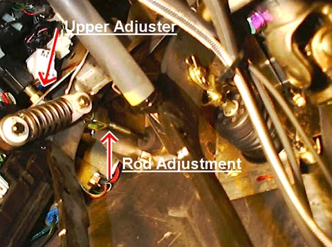
You can see the clutch pedal spring in this picture as well as the clutch adjustment rod. This component goes through a boot in the firewall (which can also be seen) and connects to the master cylinder. Just a point of interested on most cars, this rod can be turned left or right to alter the point of clutch engagement above the floor, closer or farther.
- Clutch Master Cylinder
The master cylinder is bolted to firewall in the back of the engine bay. You can easily locate it as it is connected by a short hose to the clutch fluid reservoir. While I do not have a picture of an actual master cylinder, it is as its name suggests a simple cylinder with a steel line coming out of the end. The internal piston is connected to the clutch adjustment rod. Thus as the clutch pedal is pressed, the fluid in the master cylinder is forced out of the cylinder into the steel clutch fluid line that runs to the slave cylinder.
- Clutch Slave Cylinder
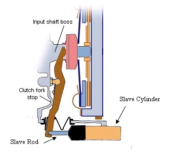
The slave cylinder is bolted to the actual transmission itself. One end of the cylinder is open to the clutch fluid line. On the other side a steel rod connects the piston of the cylinder to the clutch fork on the bell housing of the tranny. A sketch of the cylinder is show below.
Figure 2: Drawing of Clutch Slave Cylinder and Related Compenents
When clutch fluid is forced to exit the master cylinder from depression of the clutch pedal, it flows through the steel line and into the slave cylinder. The force of the moving fluid actuates the piston in the slave cylinder and forces the slave rod outwards against the clutch fork.
This covers the major elements of the clutch hydraulic system, however certain vehicles will have extra fluid reservoirs and/or restrictors in-between the two cylinders to help smooth out clutch engagement and disengagement. These are not essential components and are not discussed. Now, let’s take a quick recap of how the hydraulic system functions
· Clutch pedal is pressed
· Master cylinder is actuated
· Fluid is forced out of the master cylinder and into the slave cylinder
· Slave cylinder is actuated, forcing the slave rod out against the clutch fork
Clutch Mechanical System
- Clutch Fork
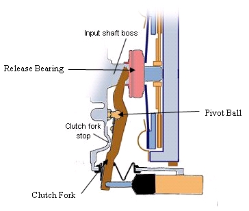
The clutch fork connects the slave cylinder to the clutch release bearing, commonly called the throw out bearing. We can see this by looking at the same figure above, this time with the fork and related components labeled.
Figure 3: View of Clutch Fork and Related Components
When the master cylinder is actuated and the slave rod extends, pressure is applied to one end of the clutch fork. This causes the fork to rotate on the pivot ball and slide the release bearing along the transmission input shaft into the clutch unit itself.
- Release Bearing (Throw Out Bearing)
As mentioned before, the release bearing is connected to the end of the fork inside the transmission bell housing and rests on the tranny input shaft and the clutch unit. When the fork swings, the bearing applies pressure to the clutch and gives the force necessary for disengagement.
- Clutch Unit
I decided to break this section up into the components of the clutch to better explain the function of the different components of the clutch itself. When a clutch kit is purchased, it contains two pieces, a pressure plate and a clutch disc. These pieces are then bolted to the flywheel.
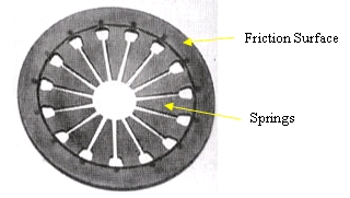
The pressure plate is simply a steel diaphragm composed of a friction surface that mates to the clutch disc and a series of extremely stiff springs. A typical pressure plate can been seen in the following picture:
Figure 4: Pressure Plate Without Cover Showing Friction Surface and Springs
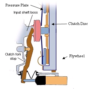
In this picture, there is no pressure plate cover. This is the often brightly colored piece that bolts the plate to the flywheel. Next, taking a look at that now familiar inner bell housing figure, we’ll look at the location of the clutch components
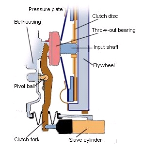
Figure 5: Location of Clutch Components Within the Transmission
Here, when the release bearing is forced against the pressure plate it causes the metal springs of the plate to bend. This bending action warps the friction surface of the plate and causes it to relax is hold on the clutch disc. Simply put this “unlocks” the clutch disc from the friction surface of the flywheel allowing the flywheel to free spin. At this point, the clutch is disengaged and everything looks like this:
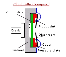
Figure 6: View of Clutch Components When Clutch is Disengaged
Figure 7: View of Clutch Unit Close Up
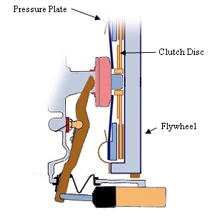
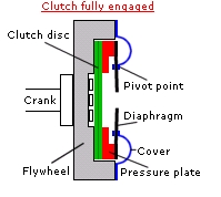
When the clutch pedal is raised, everything works in reverse, the clutch reengages and now we have a picture that looks like this:
Figure 8: View of Clutch Components When Clutch is Engaged
Figure9: View of Clutch Unit Close Up
In the first picture, the angle of the pressure plate springs has been exaggerated for the purposes of comparison between the engaged and disengaged states. In reality, the springs are completely flat when engaged, as in the second picture, and conical when disengaged.
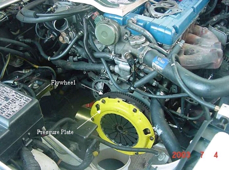
The flywheel connects the clutch and driveline to the engine. On one side it is bolted directly to the crank shaft, on the other the clutch assembly. When a clutch is installed, the pressure plate is bolted to the flywheel with the clutch disc wedged in-between the two. While there is volumes of more information on flywheels, this is the essential information relating them to clutch operation. An assembled clutch looks like this:
Figure 10: Exposed Clutch Installed on an Engine
The clutch disc is merely a disc with each side covered in a high friction material to mate with the friction surfaces of the pressure plate and flywheel. It is also the only part of the entire clutch system that connects to the transmission. The center of the disc is splined to match the splines on the input shaft of the tranny. When the clutch is engaged, the disc is wedged against the flywheel and transfers power from the crankshaft to the transmission shaft. When disengaged, the pressure plate relaxes and the disc is no longer pressed against the flywheel. Simply put, at this point there isn’t enough clamping force to cause the disc to spin with the flywheel, so no power is transferred.
Another point of interest, when a clutch goes bad, it is typically because the frication material wears out on the disc. When this occurs, even thought the pressure plate is engaged and applying a clamping force, there isn’t enough friction between the disc and the flywheel to transfer power and the clutch “slips”. This feels like the clutch is disengaged when it is actually engaged. At this point, usually the disc and pressure plate are replaced. There are many other modes of clutch failure, including explosion, breakage, warpage, etc. but those won’t be discussed here.
At this point, an overview of the mechanical aspect of clutch disengagement might help in the understanding of all this information.
To begin:
- The slave rod pushes against the clutch fork
- The fork transfers this motion and forces the release bearing against the pressure plate
- The springs of the pressure plate warp and distort the friction surface
- This removes pressure from the clutch disc allowing slippage to occur between the disc and the friction surface of the flywheel
- At this point, no power is being transferred to the transmission and gear changes can be made
When the clutch is reengaged, as in after a shift, the force from the distorted pressure plate springs actually supplies enough force to reverse the entire disengagement process and raise the clutch pedal off the floor. Thus, the pressure you feel on the clutch pedal when you depress it is the springs of the pressure plate fighting back.
Hopefully this article can help in the understanding of the entire clutch system and its function. This is by no means a summary of all things clutch related as there are entire books published on just the design of the mechanical advantage of the hydraulic system alone; however this should be a good basic overview for anyone who desires to learn just what goes on when the clutch pedal is pushed.
 AF Project Vehicle | Corporate