In lay man’s terms, degreeing your cams means synchronizing the camshaft's position with the crankshaft. A few degrees of misalignment can dramatically affect the engine's operation. If there were no manufacturing tolerances, you would only need to line up the marks on the timing chain sprockets and the cam would be degreed, but with a group of components (the camshaft, crankshaft, timing chain, and sprockets) all with their own standards and tolerances that when installed, can stack up against you. You can never be sure that the cam is in its correct position. Aside from tolerance differences on aftermarket components, changing the geometry of the compression chamber by surfacing the head or block will also require the cams to be degreed. It is always a good idea to degree the cams whenever possible.
Really, the only tools required to dial in the cam timing are a degree wheel, a stable pointer that can be mounted to the engine, a dial indicator with at least a half inch of travel in .001" increments (you’ll need a way to mount the indicator), a positive stop device to find T.D.C. and of course a set of adjustable cam gears.
While the actual process of degreeing with the engine in the car is different for every vehicle (i.e. check the forums to find out the best way to get to the timing components of your vehicle) I’ll cover a brief run through of what needs to be done once the timing components are accessible.
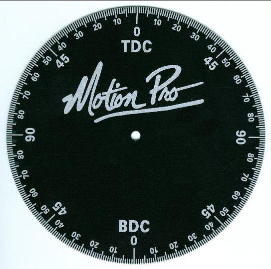
First, for safety, disconnect the battery; you won’t be using the starter to rotate the engine AT ALL. In order to take readings the degree wheel and pointer need to be mounted to the engine. The degree wheel, like the one seen below, mounts to the crank sprocket.
Next fix the pointer securely to the block so that it will not move. Once the degree wheel is on the next step is to find Top Dead Center on any cylinder (preferably #1). To do this, first rotate the engine to approximate T.D.C. Line the pointer up at zero on the degree wheel. Now rotate the engine to move the piston down into the cylinder. Install your positive stop device into the spark plug hole and extend the bolt. Next hand turn the engine, rotating until the piston comes up and stops against the bolt. Look at the degree wheel and write down the number of degrees shown by the pointer. Turn the engine by hand in the opposite direction until the piston comes up and stops on the bolt again. Go back to the degree wheel and write down the degrees it now reads. With both readings, add them together and divide by two. At this point, move your pointer by this many degrees and rotate the engine again making sure that the readings on each side of T.D.C. are equal degrees away from zero. If they are, the number on the degree wheel the pointer indicates will now be the true T.D.C. point. Lastly, remove the positive stop device from the spark plug hole.
Once T.D.C. has been found, the next step is to measure the actual cam timing.
Before anything else, in order to get accurate readings, the hydraulic lash adjusters (lifters) must be set to zero lash. There are mixed opinions on the best way to do this. Some people take the factory lifters and compress them flat. They use washers to shim the now ‘solid’ lifter up to the follower creating roughly zero lash or slight negative. In the case of negative lash, the lifter sits just below the follower. Another method requires some spare lifters but is a little better. Disassemble the two spare lifters (one for an exhaust valve and one for an intake valve) and place a small segment of threaded rod with two locknuts inside the two halves of the lifter. By moving the nuts up and down the rod you can adjust the height of the ‘solid’ lifter. Feeler gauges are necessary to determine when zero lash has been reached. For most people dealing with the lifters is the most time consuming part of the whole process.
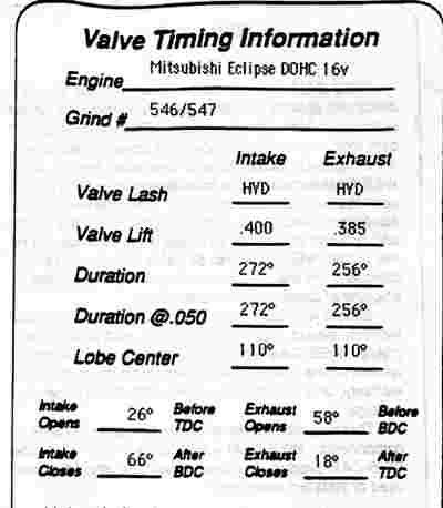
Now is the time to pull out the spec sheet for your cams. Shown below is a sample sheet for a set of DSM cams.
What you want to look at is when the intake and exhaust cams open and close, the lobe centers of each cam, and the specified lift at which you measure duration.
With the lifters set, situate the dial indicator so that the tip is on the retainer of the valve you are measuring and the range of travel of the indicator is perfectly parallel to the valve movement. This is especially critical as you are measuring the rotation necessary to open the valve to a specified distance. If the dial indicator is off-axis, the geometry introduced will skew the readings. With your dial indicator on the retainer or follower, rotate the engine in the direction it would normally turn, and come up to the lift specified on the spec sheet. Write down that the number of degrees shown on the wheel at this point. This is your opening figure. This is when the intake opens before Top Dead Center. An example would be 15 degrees on the degree wheel B.T.D.C.
Now go over the top on the lobe until your indicator is again at the specified lift. Now you should be where the intake closes after Bottom Dead Center. Keep in mind to continue turning the engine in the same direction it runs and do not back up. Here an example would be 45 degrees on the degree wheel A.B.D.C.
With these numbers you can calculate your duration. The valve opens at 15 degrees, plus it closes at 45 degrees, plus 180 degrees. (The extra 180 degrees is because the crank turns twice as fast as the camshafts) Your duration at the specified lift would be 240 degrees. (15 + 45 + 180 = 240) Now you can calculate your lobe center by dividing your total duration by 2 and subtracting your intake opening figure. (This would normally be the smaller number of the two) (240 / 2) - 15 = 105. This is your lobe center.
Once you have found the lobe center you simply compare that number to the center given on the spec sheet. If the lobe center is less than the spec your cam is retarded too much. To get the cam back in spec, advance your cam gear the difference between your measured lobe center and the spec center. If your measured center is larger than spec, retard the cam gear to compensate. With the cam gears adjusted go back and double check that your cam is dialed in to spec. If it isn’t, repeat the process. If it is, move on to the other cam. (If applicable)
A car with properly degreed cams will make more power than a car with undegreed cams. And as an additional bonus, with the cams dialed in properly, things such as idle, response, and drivability tend to improve as well. Hopefully, you now have a better understanding of the process you can use to make sure your expensive aftermarket cams are performing the way they should.
Notes:
- Always check all clearances and check for valve spring coil bind when degreeing in cams.
- From a tuning perspective, if you want to start adjusting lobe centers (advancing/retarding individuals cams) in search of that last few horsepower, keep in mind that if you move the lobe centers closer together it will usually give more low to mid range power. Moving the lobe centers apart usually gives you more mid to top range power.
- If you have a low overlap cam, the intake opening may be after T.D.C. If this is the case, you will have to subtract the intake opening figure from the closing number and add 180. This will be the duration. (45 - 15 + 180 = 210) Next, divide the number by two and add the opening number. (210 / 2) + 15 = 120. This is how you arrive at the lobe center. The same thing can happen with the closing number on the exhaust cam.
 AF Project Vehicle | Corporate